Methods: Construction Manual, Construction Standards, and Photo Assembly Guides
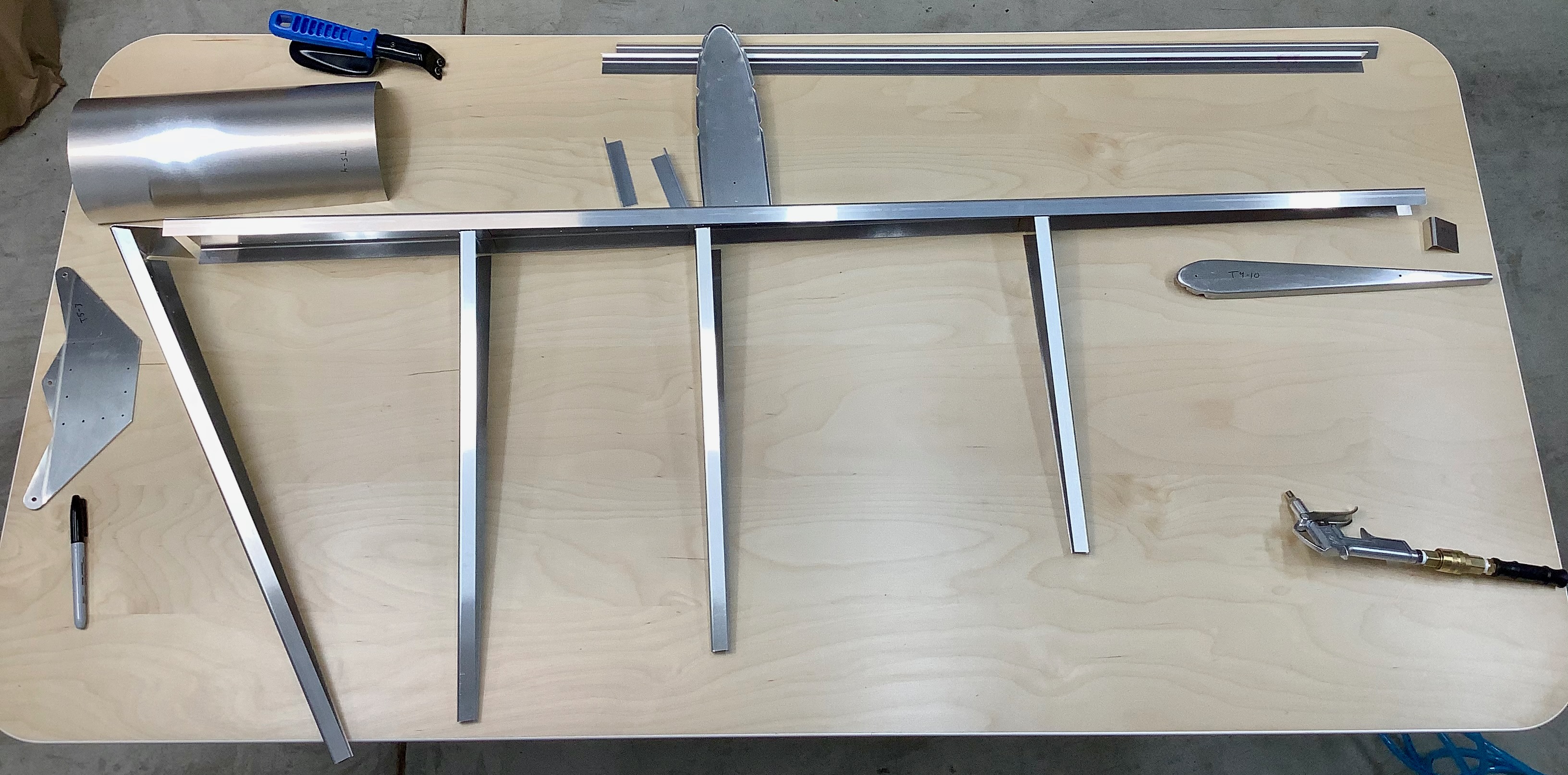
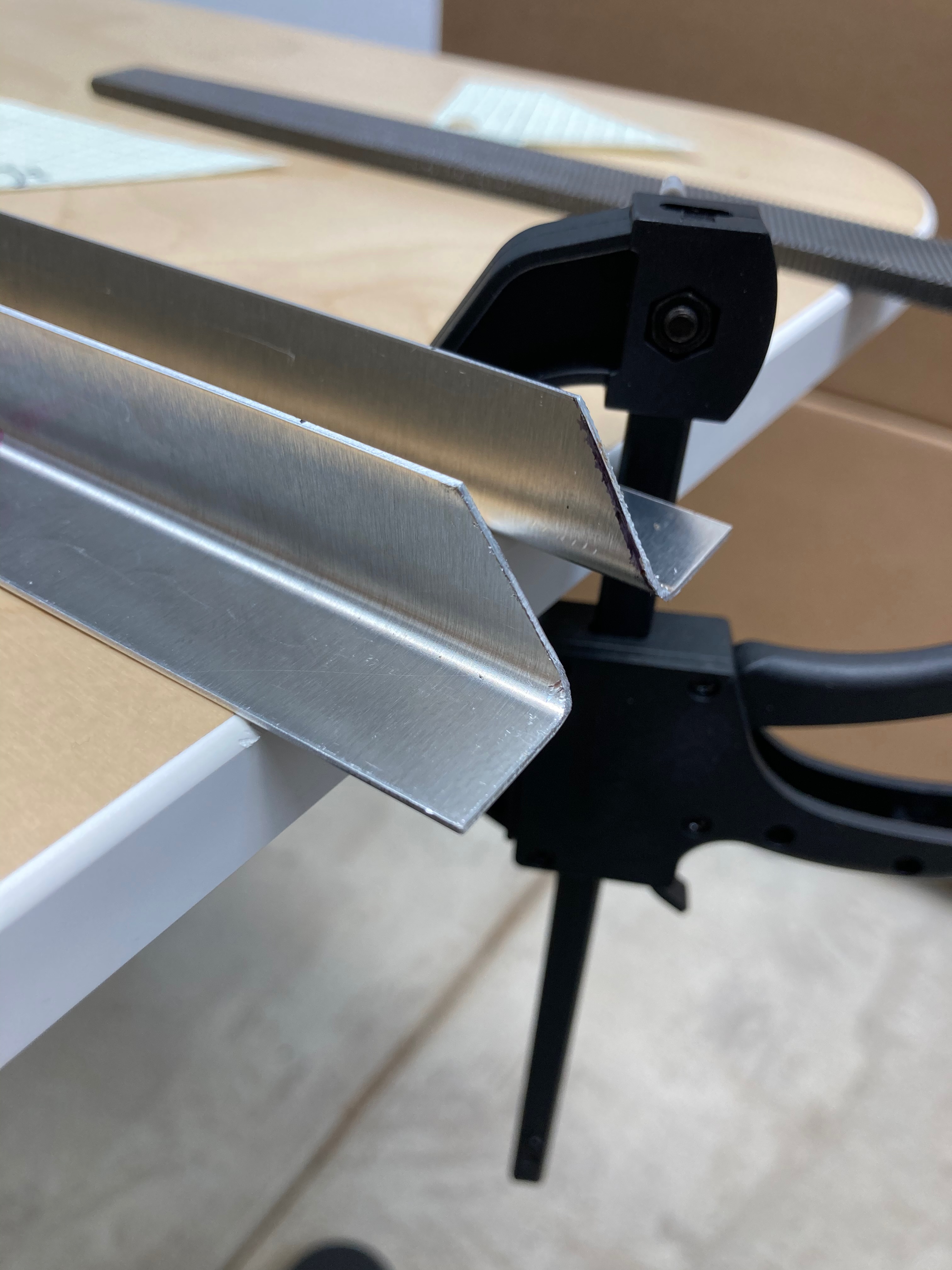
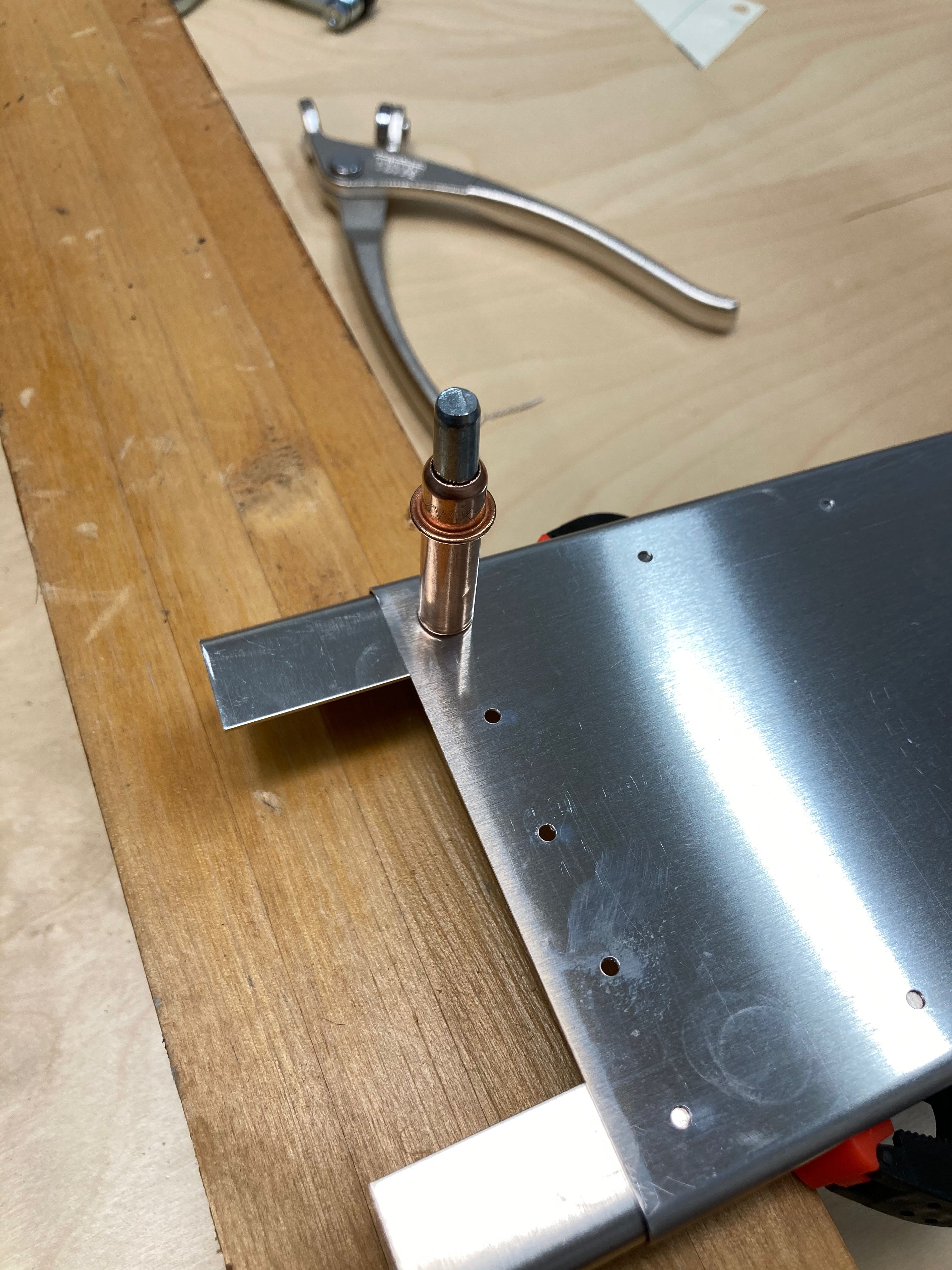
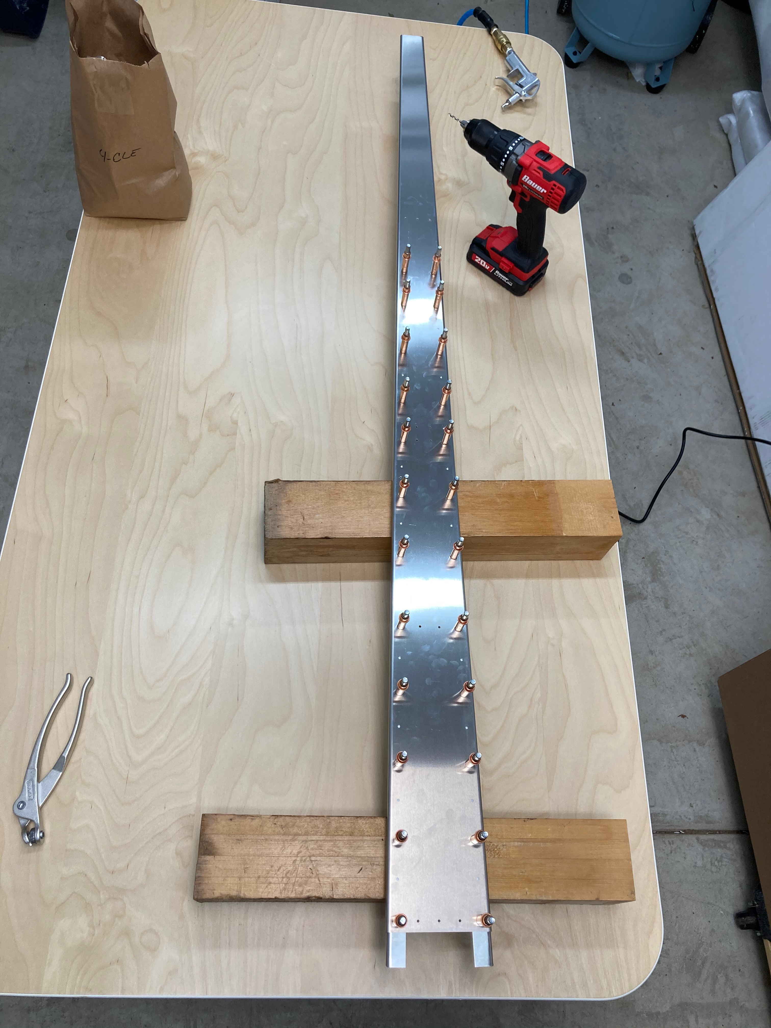
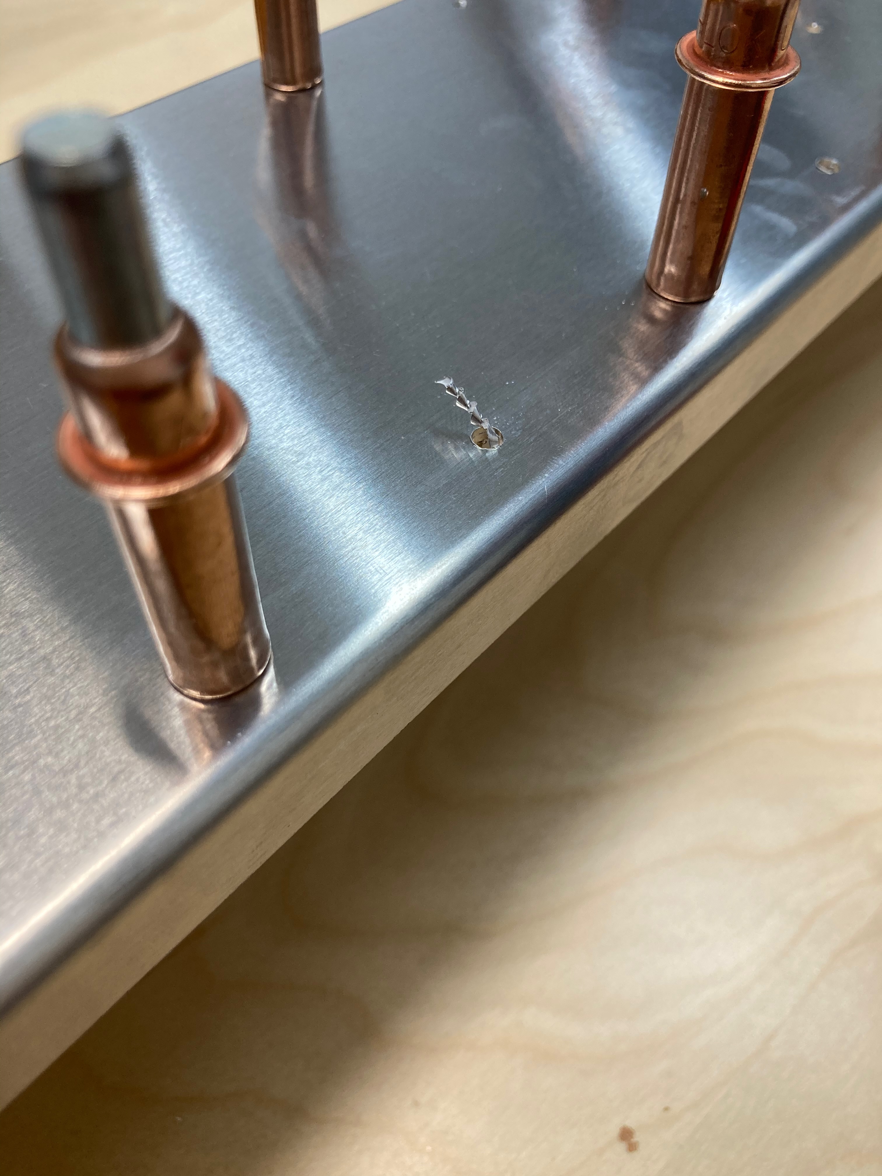
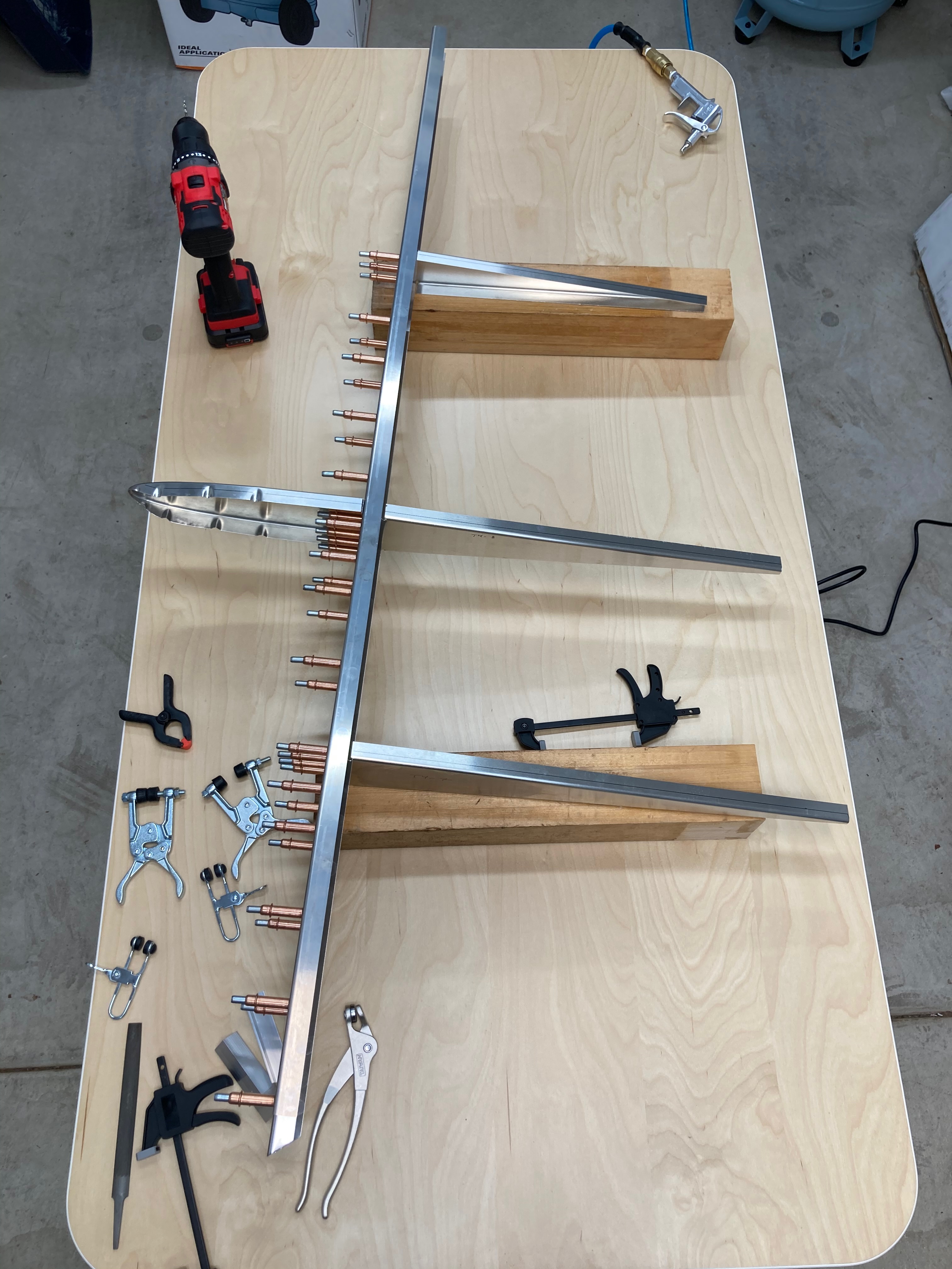
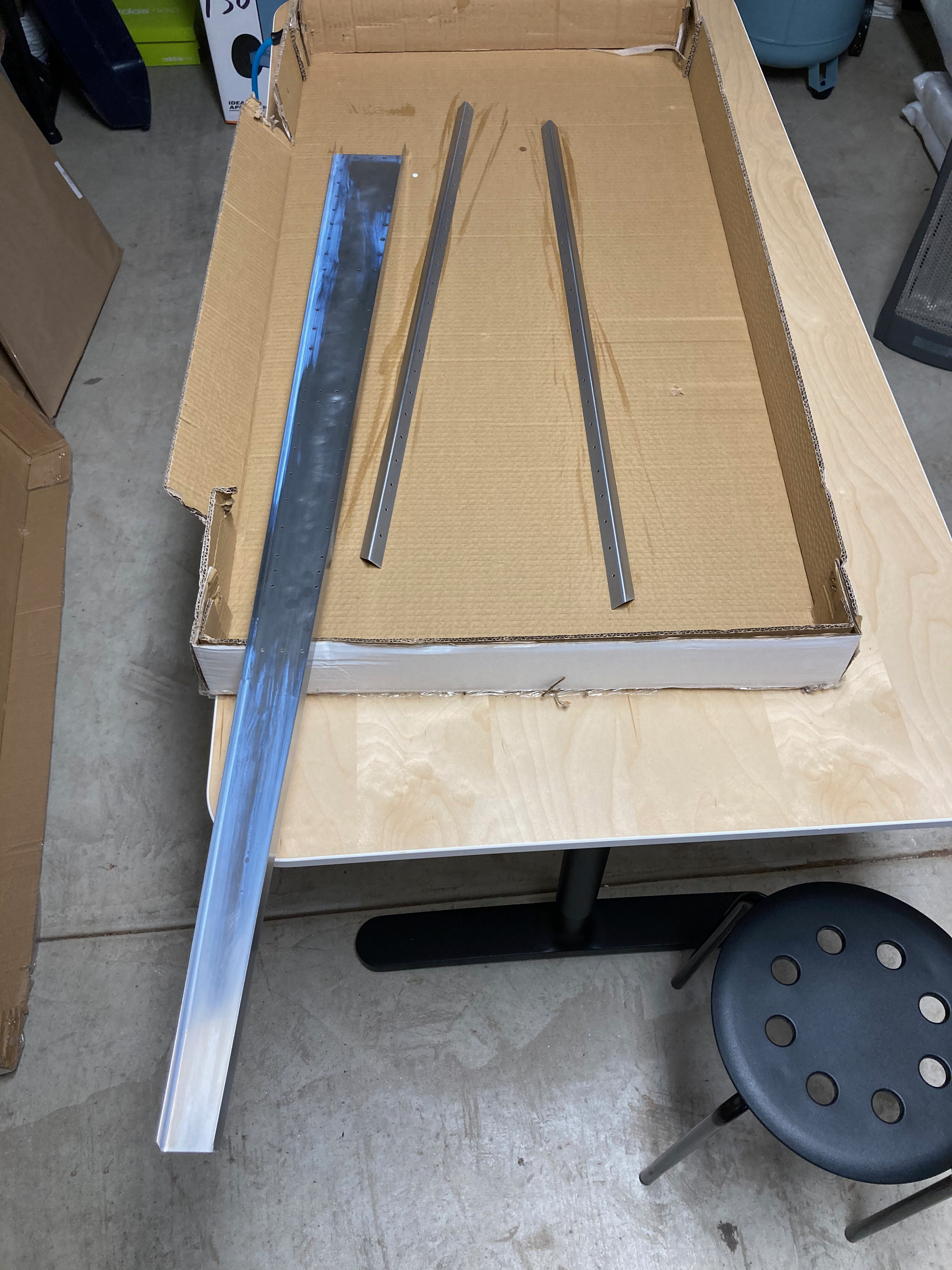
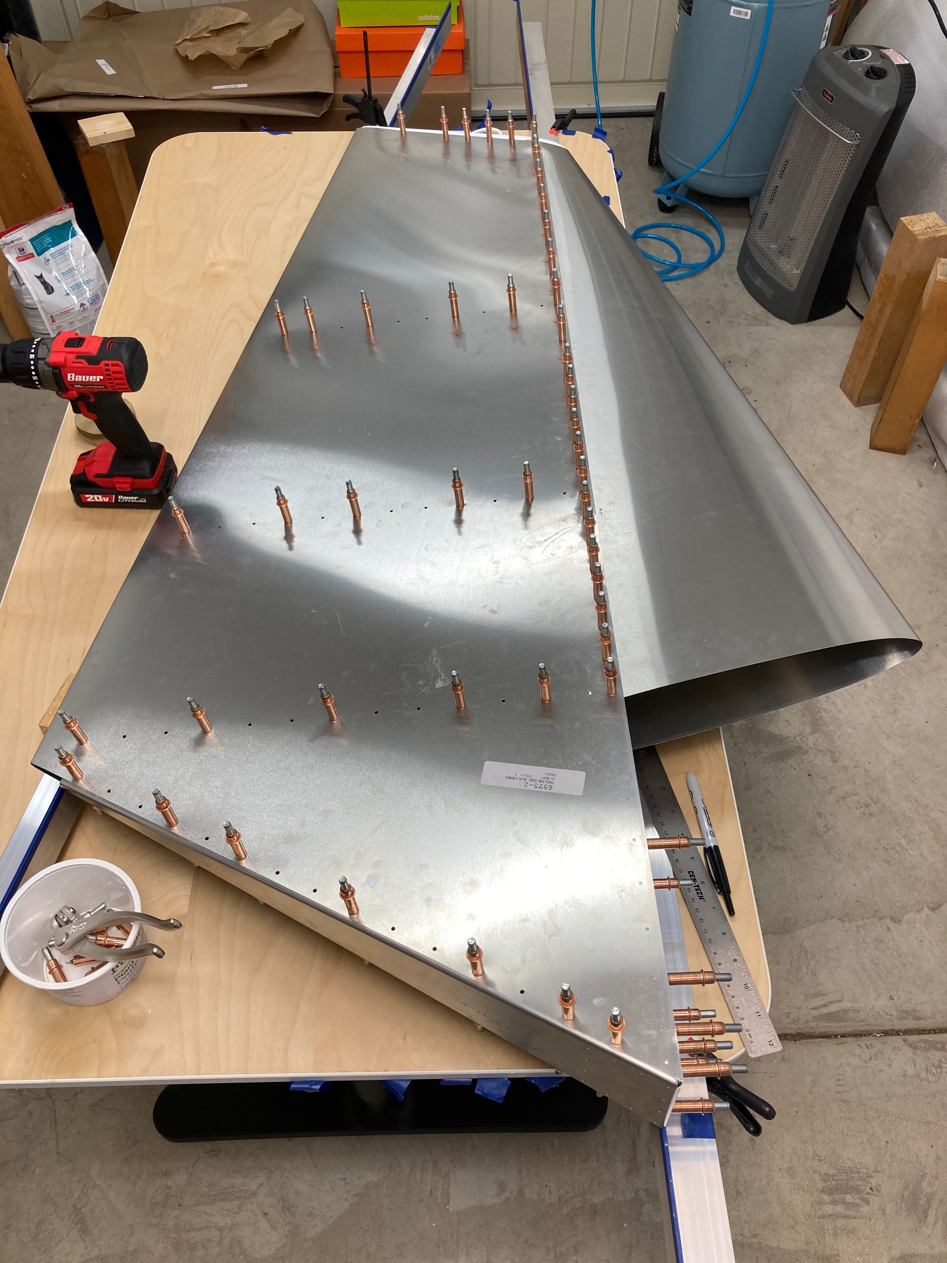
Rudder skeleton parts were first laid out to get a sense of how they fit together.Bottom corners of the 65-T-4-5 rudder spar doublers were trimmed to form a 33˚ angle.Holes were drilled and my first cleco set in the 65-T-4-4 vertical tail spar and 65-T-4-5 rudder spar doublers.Moving along the spar, more holes were drilled along the vertical rudder spar and doublers.My first burr emergin in a spiral form from a hole I drilled. I cleaned up the burr and refined my drilling technique.Next I moved on to drilling the rudder ribs and fastened them onto the spar.Once all parts were finished with fabrication, I strategically applied cortec (for corrosion control) where metal will meet metal.Now it is starting to look like a rudder. Both leading and trailing skins are fitted to the skeleton with clecos.